My Multibot - Initial development
I am building a multibot 3D printer, with somewhat similar features to the one by @Shauki on Maker Forums and OpenBuilds.
Please click 'Read More' below for full details.
Shauki's Multibot on Maker Forums
Shauki's Multibot on Openbuilds
Shauki has done excellent work and has made great contributions not only in this and other projects, but also in getting me to think about what is needed and possible.
If anyone else is working toward these or similar goals, I would like to collaborate with you and welcome participation (to a point, I only have one body, one mind, one wife, one mother, 4 children, one grand child and one dog, all of whom require my attention from time to time).
Design Goals
Obviously I have different design goals from those of Shauki, here are the important ones in no particular order.
- This is essentially a Fused Filament Deposition Printer
- Everything must be pluggable, replaceable and instantly upgrade and downgradeable
- Significantly reduce the number of failed prints
- Significantly reduce print times.
- Provide a platform to enable, support and promote experimentation
- Everything should rely on 'single version of the truth'.
- (Over) constraint and (mis) alignment is to be managed in the design.
- Fully enclosed environment
- Reliability in face of power failure, missed steps, jams, stock outage
- Closed loop control of all motion.
- Redundant sensors to improve reliability
- Must be able to handle multiple concurrent materials and tools (colour, ceramics, laser etc)
- Hot swappable parts, mid print, must configure and calibrate themselves
- Must detect, compensate for and correct common problems and faults
- Don't redesign what works, don't retain anything simply because it is a de-facto standard.
- KISS (Keep It Simple Stupid) - Complexity, if present, must be hidden from the user
- Pick up existing standards where relevant
Initial Implementation
I have added a few local conditions that define my implementation.
- Must fit on a desktop 600mm deep. A 500mm cube was my original thought.
- Would like to use 450mm MGN7 rails I already have
- Prefer to use standard aluminium profiles as they are cheap, stiff enough and light.
- Would like 3*3 or 4*4 (9-16) printing and mixing heads in this volume.
- Initially constrain printing to a single Z layer at a time.
- Use spares in my junk box
- Battery operation (my mains power supply is not reliable with frequent 4 hour outages)
- Not a Reprap. Machined components are OK, especially if made on my home made CNC.
Some of the artefacts developed may be applicable to SLS, SLA and other 3D printing techniques, but this printer is essentially going to fuse bits of plastic (usually filament from spools of feed stock) to additively manufacture an artefact.
I wanted 500mm cube container, but opted for a piece of MDF 650* 530 in my workshop.
I used 430mm * 16mm stainless steel tube as verticals, also on hand. This defined the basic 'Greek Temple'. I knew this would suffer racking, which can be cured simply (When in doubt take a hammer, the bigger the doubt, the bigger the hammer).

I want to keep the outsides of the 'Greek Temple' clean so that I can enclose in glass without extending the dimensions. This has not proved easy, but I will work on it.
Print Times
I believe that the item that most limits the application of 3D printing in all its forms is
the restriction of printing to a single, small nozzle.
Second to this is the ability to provide consistently melted and measured plastic to the nozzle such that the filament is evenly sized and adheres to its substrate. Stringing and ooze must be controlled.
Third is the ability to produce consistent and accurate bridges. The lack of this ability results in the need to print support material.
resolving these issues opens whole new fields of application for 3D printing.
Improving maximum printing feed rate from 50mm/sec to 500mm/sec and beyond is being done already. Improving acceleration and nozzle dynamics is probably more important for the majority of (small) prints. This will require better control of the print tool, nozzle and extruder.
Increasing the number of concurrent print heads, can improve print time by a further order of magnitude.
Achieving both these goals will redefine the industry.
Bridge production is largely about controlling the filament position after it leaves the nozzle.
To achieve this, print heads need to be made significantly smaller and lighter. Drive electronics and mechanics must also improve.
Failed Prints
Another inhibiting factor for 3D printing is the percentage of failed prints.
Hobbyist machines (and some professional ones too) are prone to print failures.
Most of this is caused by the lack of real time feedback from the end effector to the control software that instructions have been followed properly.
The project will add real time feedback and error correction and containment features in order to provide on-time correct delivery of artifacts.
In order to achieve this, many aspects of the tool chain need to be adjusted.
'Single Version of the Truth' mechanics
This was taught to me both by my father, an engineer, and at engineering school.
It is all to easy to over constrain the mechanics of a Cartesian bot, and some way needs to be found to retain accuracy, stability without the system jamming due to temperature changes and mechanical assembly.
During development of this and other bots, I have frequently found that my 'excellent designs' suffered jamming as a result of over constraint.
The remedy is always to select a single axis member as 'true', then provide sufficient additional constraint (usually rotation about the axis) to achieve a plane and normal for the member on the axis.
Design, manufacture and setup then ensure that that all axes are either normal or parallel to each other.
My intention is to use accurate machining of parts to supply an accurate and rigid Cartesian frame. I prefer shims to adjusting screws as they are measurable, provide finality and do not shift with vibration or wear.
Final correction may be achieved through software transforms in the event that mechanical correctness is difficult or impossible to achieve.
Software feedback by measurement should be redundant so that the system can self check and cope with individual part failures. This, to some extent, contradicts the 'single version of the truth' requirement, but is seen rather as a method of coping with single point of errors and failures in the electrical and electronic component.
Electronics
My initial implementation uses two STEVAL-3DP001 boards. They each provide
- 3 positional motors,
- 3 bed heaters
- 3 extruders and hotends.
- WiFi and USB connectivity
- SD card for configuration and printing.
These are not ideal, but will, provide sufficient to get the two gantries moving independently. By providing an off board Z drive, it is possible to have 2 gondolas and a total of 3 hot ends per gantry.
This is sufficient for proof of concept.
The board has software based on Marlin 1.1x and is in the Marlin 2.0 build which I have not as yet got operational. I have a few RAMPS, GRBL, A4988 and STM32 boards lying around to rope in as required.
The board provides 6 stepper drivers, and is designed for a 3 way mixing head, or three hot ends co-located on a single gondola.
The board has IO limitations that do not easily enable closed loop feedback and other nice to haves that form part of the project. Though it remains to be seen what can be done with the existing interfaces.
The STEVALS have sufficient resources to drive either a 3 colour mixing head or two independent single colour print heads. This is sufficient for starters.
I can also use spare ADC channels to provide positional feedback of the gantry and gondolas.
My aim is to redesign the software and electronics anyway. So for now it is just to get something working.
My previous builds culminated in two machines built on Durst enlargers and discarded dot matrix printers.
Here is the bigger one, it sports a 900mm column and a Lexmark printer for X. Y is provided by an old Apple Image writer. All the motors are effectively Nema23s, and it can hold an awesome speed and acceleration.
The Lexmark was capable of 500cps or 2-3 traverses of the 300mm wide paper per second. The hotends I am using stop producing sufficient melt above about 120mm/sec, though for low quality work I can push 200mm/sec.
 |
| 3DP built on a Durs M800 Enlarger, Lexmark and Apple printers |
Here is the other one, built on MGN7 rails and currently fitted with a 405nm 0.5watt laser.
 |
| Built on a Durst M608 enlarger, linear rails, replaceable head. |
Both use RAMPS.
They are both have very solid Z axes, capable of 800mm and 600mm respectively. I needed to make some adjustments for broken pieces and add motors to the rack and pinion drives, but overall they are pretty much as is. They cost me about US $7 each, I can probably get double my money back from the lenses they came with.
The printers cost the same.
Plug-ability
One of the design goals is to provide both mechanical and electrical plug-ability.
Unfortunately there are no standards to talk of, and little is being done in the community other than perhaps the E3D interchangeable tool heads.
E3D seem to be doing a superb job, as they always do, but I am not sure if their solution is going to be compact enough to suit my design goals.
Reprap have some standards (RIS) which form a convenient basis but are really only a start to a much wider requirement.
When building a multibot, standards become a necessity. For example the RIS provides a nice, compact hot end format, yet does not constrain the length of the J-head, but offers 2 options (36.5 and 50mm). So one is forced into adapters and taking a less attractive option.
My E3D seems to be 43mm. There is also no standard or the distance between the mount and the tip of the nozzle, in my mind, a much more meaningful measurement.
Some clone nozzles I bought are 50mm long.
What is clear is that we need, as a community, to start thinking of standards for plugging modules rather than components. All of this becomes much more of an issue as we move to multibots. I will not be keen to replace 20 or 30 hot-ends, mounts and cables simply because the old ones went out of fashion.
For now, my development will attempt to retain RIS and perhaps provide some options that can be debated, accepted or rejected as we gain new experience.
The 'Object Oriented Design' principles I am familiar with from a software development perspective could provide a basis under which we can go forward with standards that meet the design goals of a range of machines. More of that later in a separate blog.
I want to be able to replace an entire axis mid print. At this time it may not be possible to get back to the Zero position in at least X and Y. Ideally all print heads are positioned an exact distance away from the mounting point, and the mounting point can be calibrated and either does not rotate or knows it's rotation.
Wiring
Here is a typical RAMPS 1.4 wiring loom on a dev machine. Actually its been in production for over 2 years, and is quite stable , despite the press-stik. Stability is provided outside the picture :-)
 |
| A typical RAMPS wiring harness |
I cannot see any standard developing for the wiring harnesses and connectivity that will be needed as the bits and bobs of a 3D printer evolve, and better interchangeability and extension becomes a requirement.
I want to define extensible standards for at least
- Hotend
- Extruder
- Single Axis (motor, end stops, feedback)
- Heated Bed
- Dual Axis chaining (e.g. Y mounted on X, or X mounted on Z)
Plugs must be reasonably priced, secure and available globally.
Axis Concept
Assuming a 200*200mm build and 450mm axes.
There is 450-200mm (200mm) of available space on an axis for several gondolas to share.
This 250mm could be shared by 4 gondolas each 50mm long (200mm).
This results in an area 250mm*250mm for any gondola to work in if the other gondolas are sent to the extremities. There would be 16 such spaces in a 4*4 arrangement, and all we need do is ensure that no 2 gondolas occupy the same space.
This can be solved using scheduling and priority algorithms that pick traces to print from a pool of traces on the current level.
It should be possible to print more than one trace simultaneously much of the time.
The result is a much faster print, printing time decreasing by the average number of print heads simultaneously active.
The real result can only be found by developing algorithms, simulating and testing them.
In any event, substantial reduction in print time can be achieved, especially when parts are small compared to the overall print volume, or where a substantial portion of the build space is occupied.
Z Mechanics
My initial plan was to use 3* 8mm*8 lead screw to provide Z motion. I then wanted to use accellerometers on both the chassis and build plate to provide constant, automatic tramming.
Difficulties in constraining the build plate in X and Y resulted in a rethink, and I took Thomas Sandladerer's advice that the Z plate level should be engineered and constrained correctly.
I have a small Nema 17 pancake motor geared 50:1 that I will test against a 12mm*3 lead screw and two 12mm shafts. These screws are about the same price as 8mm, and I had a small length available that suited.
In case the Z drive proves inadequate, I have a Nema23 * 76mm geared 7.5:1 that can lift my Honda.
The end stop slides on one of the shafts.
I am waiting for a new 12mm shaft for the left hand side.
 |
| Zaxis, 12mm rods, 12mm lead screw. |
At this stage I have not provided closed loop control on Z. This will be done either through an encoder or a potentiometer.
Y Mechanics
The Y mechanics consist of a MGN7 rail mounted on a 50*25mm aluminium square tube.
There is a GT2 belt driven by a Nema 17 motor with a 10 turn pot at the distal end to provide positional feedback.
I milled and drilled a piece of LDPE (85*50*10) for the carriage. I tried 3D printing this piece, but found that the accuracy was insufficient, resulting in the dual carriages binding because they were misaligned by fractions of a milli meter.
The arrangement seems stiff enough to support a semi cantilevered design. At the moment, I have the distal end supported by a similar block. This block will be remade to fit a single MGN7 block, and release the constraints in X and Z rotation. This will cater for Y rail misalignment. I will need to compensate for Y rail misalignment in software (single version of the truth).
The use of 2*MGN7 carriages seems to be sufficient to control the yaw of the cantilever, but it limits the carriage to a minimum length of 48mm. This is slightly longer than the 42mm of a Nema 17, but the extra is probably needed to get the other components on the gondola.
Positional feedback is provided by a multi turn potentiometer. This provides 400 mm of travel with 12 bit (4096) digitisation. This should provide 0.1mm or better resolution by oversampling and other techniques provided by ST.
 |
| Y Axis. MGN7 rail, machined HDPE carriage. |
 |
| Belt tension and clip. Friction is sufficient, but can be clamped using a 3mm bolt |
Still in dev. The motor needs to be lifted a fraction. You can see the belt tightening arrangement.
You can see the additional MGN7 block for the second gantry.
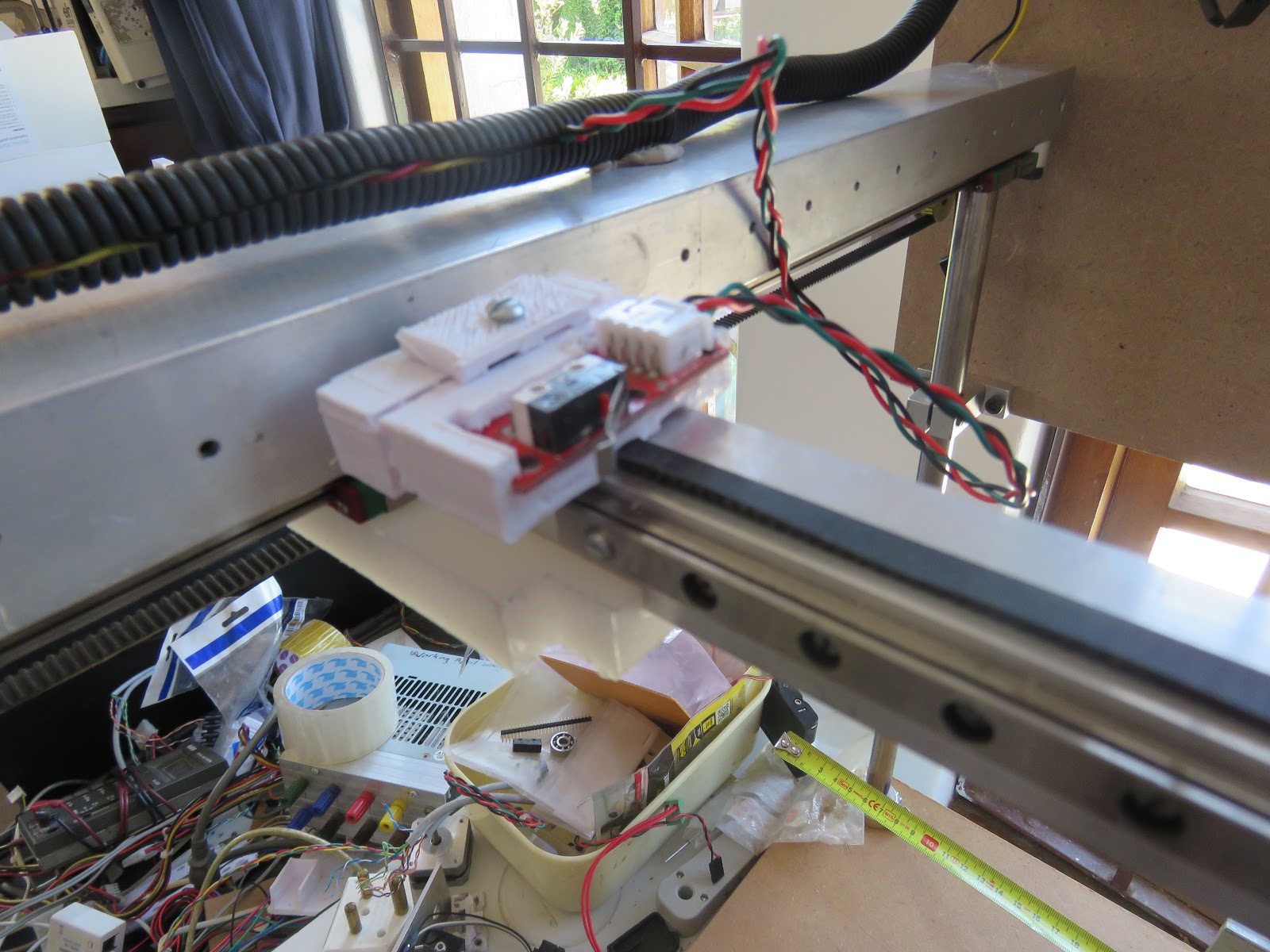
Here you can see the X axis about to be clipped into the milled out section on the LDPE of the Y axis. I have provided 2 bolt holes that allow me to clamp the X axis into the Y carriage.
You can also see the belt tightening arrangement for X.
The whole hot end can be removed with the filament in place by removing the clamping bolt and sliding the filament through the clamping gap. By using identically set hot ends, it is possible to change colour, material and correct nozzle jams mid print.
 |
| X Gondola with X Drive motor and E3D hot end. |
The arrangement provides 300mm of travel between two sets of carriages.
The build volume can larger since the hot ends can be placed on opposite sides of the x axes. This yields about 380mm of build length. This can be further extended by positioning the outer hot ends further away from the rails. I aim to be able to get 500mm in Y by suitable positioning of the components.
X Mechanics
The X axis is similar to the Y axis but is built on 20mm square aluminium tubing. This tubing is about 1/3 the price of 20mm profile and much lighter, which, I hope, will provide better acceleration and faster print speeds.

The X Drive motor is travelling t this stage, as this was the easiest to think of and implement.
It also provides a simple mechanism for running two gondolas on a single gantry. In this case, one could have 2 nozzles, and the other a single nozzle.
I think there is enough space to place a X motor at each end of the gantry without interfering with movement of the gondola, or inhibiting interchangeability. If I do this, I will try a direct drive extruder motor on the gondola.
The motor is a Nema17 * 15 salvaged from a hard drive (when they still used steppers to position the heads - probably 1994). These ones are 0.9 degree per step. I can now get 1.8 degree equivalents.
 |
| X End Stop. I may move the X Drive motor here as I have sufficient space for two drive belts. |
The cable trunking is temporary as the box section provide space to act as conduit.
There is a bit of positioning going to happen in order to optimise the gondola.
The motors being used are 42mm cubes by the time the shaft and pulley is attached. I have a lower limit of 48 in X and Y due to the dual MGN7 carriages. There is no real need for two carriages in X fo r the gondola, so the X limit can reduce to 42mm for the Nema17, or even less if smaller motors are found to be adequate.
At the moment I have 68mm in X and 58mm in Y. The need to use a cooling tower and route filament past the motor contribute significantly to this size.
Some obvious optimisations will reduce this to 56 * 42.
I have yet to check my Z dimensions as final optimisation of the gondola will involve balancing X,Y and Z options.
With a single X carriage, I get about 380mm of travel on 450mm rails.
A mixing head or 3 or 4 nozzle head with fewer carriages seems a likely candidate for the current round of experiments.
There is no positional feedback at this stage.
Extruders and Hotends
The current plan is to use standard Bowden extruders that clip over the Y axis box section.
The extruders themselves are off the shelf parts which may need to be reassessed as experience is gained and new constraints, options and opportunities present themselves.
I have a variety of extruders and motors to try out. I haven't used Bowden tubes before as I have always had sufficient torque to throw a motor around with a head weighing up to 450gm (1 pound).
My intention is to get far away from this and provide systems capable of printing up to a meter a second or so. I believe this to be possible at the hobbyist level.
I would like to add filament out indication as well as filament motion feedback.
Having a plugable design, I intend to develop a number of light weight extruders and hot ends.
There is a lot of stasis in 3D printing, and I feel much of it is due to the choices made in the initial proof of concept developed by Adrian Bowyer and his team ten years ago. The choices were entirely valid and probably correct at the time, but the IT industry has moved on significantly as it always does, and there may be opportunity that can be exploited from the huge amount we have learned in the interim.
I will always be indebted to Adrian and his team for their incredible contribution to this amazing industry.
For the begining thanks for giving credits and please activate subscription in the blogger settings.
ReplyDelete